555 Timer Circuit Diagram Project
555 timer diagram block circuit chip does ne555 datasheet pinout inside work works eleccircuit look function Simple motion detector using ne555 timer circuit 555 timer ic circuits schematic datasheet blok circuitstoday flop astable adjustable transistor rangkaian proteus
Dancing Light using 555 Timer
555 timer circuit using light dancing circuits diagram easyeda pcb chip pulse based cloud software ne555 555timer projects lm555 time Timer rangkaian lampu disko easyeda pcb skema electrosome 555 timer circuit circuits ic diagram testing supply power input 15v ends terminals 1x2 1x1 provided must between
Motion circuit ne555 detector using timer simple diagram electronics projects electronic circuits fig applications security
Timer ic 555 testerHow does ne555 timer circuit work 555 timer circuits555 timer schematic : 555 timer circuits in proteus : in this category.
Diagram led chaser 4017 555 circuit timer using capacitor wiring start counter motor run off ic phase electrosome shut mechanical555 tester ne555 engineeering Dancing light using 555 timer.


Dancing Light using 555 Timer

EasyEDA - A Cloud based PCB Design Software

timer ic 555 tester | Best Engineering Projects
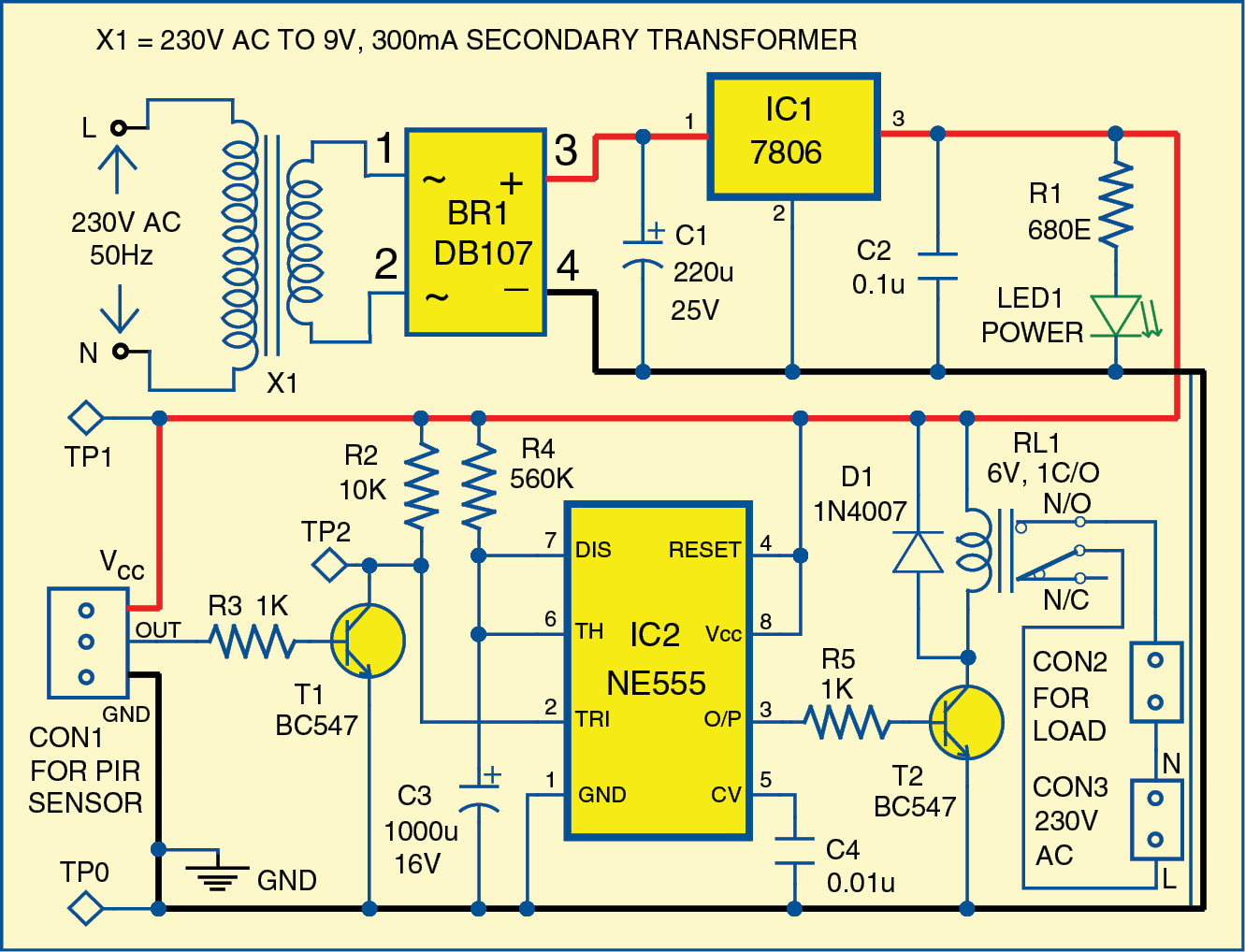
Simple Motion Detector Using NE555 Timer Circuit | Electronic Circuits

How does NE555 timer circuit work | Datasheet | Pinout | ElecCircuit.com

555 Timer Schematic : 555 Timer Circuits In Proteus : In this category

transistors - led chaser with non-mechanical shut-off option